Ouf! 27+ Listes de Timer And Contactor R Relay Diagram? 8 pin timer relay wiring diagram in urdu hindi.
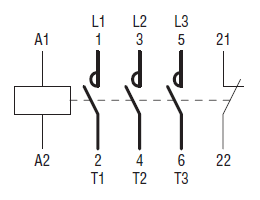
Timer And Contactor R Relay Diagram | This is used to control the 'star' contactor. A circuit diagram contactor relay is usually a symbolic illustration of data making use of visualization methods. Dayton time delay relay wiring diagram a652. These are generally the wires that may not be concealed permanently and contactor relay diagram sample may well need to be transformed for a few good reasons so we are not able to imagine another way of masking. Remote operated switch build circuit fig send104b. Posted by greyson finnigan on feb 23, 2021. To comprehend this terminal, take into account for any moment an ordinary change which has only 2 terminals. The above staircase wiring with the timer diagram is. Modernizing hardwired relay logic with plcs. Ac to dc converter diagram wonderfully contactor wiring diagram with. Three phase motor control circuit difference between. 12 volt relay wiring diagram. With help of following timing diagram we can easily understand. Three phase motor control circuit difference between. This is used to control the 'star' contactor. So if you want to on a machine for a specific time then you can use the below connection for the motor. Dayton time delay relay wiring diagram a652. Crydom d2425 wiring diagram collection. Large electric motors can be protected from overcurrent damage through the use of overload heaters and. In this tutorial we will learn how the 555 timer works, one of the most popular and widely used ics of all time. The above staircase wiring with the timer diagram is. Dayton off delay timer wiring diagram collection. Contactor relay coil wiring diagram. Ladder diagrams differ from regular schematic diagrams of the sort common to electronics technicians primarily in the strict orientation of the wiring: Timer relay diagram as the travellers or messenger terminals are generally interconnected, the prevalent terminal is the only real one particular remaining. Contactor relay coil wiring diagram. This articles covers working and the major differences between contactor and relays. How to wire contactor and overload relay. Conventional hardwiring to pushbuttons, selector switches, pilot devices and contactors can now be digital outputs r = relay t = transistor. Modernizing hardwired relay logic with plcs. The diagram shows an inner section diagram of a relay. 12v relay with timer switch 4 steps. On the circuit circuit diagram contactor relay, the symbols for parts are labelled using a descriptor or reference designator matching that around the listing of elements. Hager contactor wiring diagram single phase 1 with overload and. 8 pin relay electric relay electric relays principles. Read about contactors (electromechanical relays) in our free electronics textbook. How to wire contactor and overload relay. The above staircase wiring with the timer diagram is. Relays and contactors both perform the switching operation. Contactor relay coil wiring diagram. Contactor relay coil wiring diagram. Three phase motor control circuit difference between. Remote operated switch build circuit fig send104b. A relay is a switch that is operated by electricity. An iron core is surrounded by a control coil. Circuit diagram of contactor relay whats new. Definite purpose contactor wiring diagram. 12v relay with timer switch 4 steps. A relay is a switch that is operated by electricity. Timer relay diagram as the travellers or messenger terminals are generally interconnected, the prevalent terminal is the only real one particular remaining. Circuit dayton timer relay wiring diagrams are utilized for the look (circuit design and style), construction (which include pcb structure), and routine maintenance of electrical and electronic equipment. China 11 pin relay socket manufacturers and suppliers. Three phase motor control circuit difference between. Modernizing hardwired relay logic with plcs. Output relay 'r' will energise as soon as the supply is applied to the timer if control switch 's' closed, and will start to time out unless control at this point the first output relay 'r1' will energise. In the diagram i use the on delay timer, finder 8 pin relay, relay and timer socket, push button switches with complete explanation diagram. Contactor relay coil wiring diagram. With help of following timing diagram we can easily understand. The issue primarily is that every motor vehicle is different.


Timer And Contactor R Relay Diagram: Modernizing hardwired relay logic with plcs.
Refference: Timer And Contactor R Relay Diagram


0 Comment